If you’re on the fence about getting a CNC router, then this is the post for you.
Let’s take a look at the core workflow used to run a hobbyist CNC router.
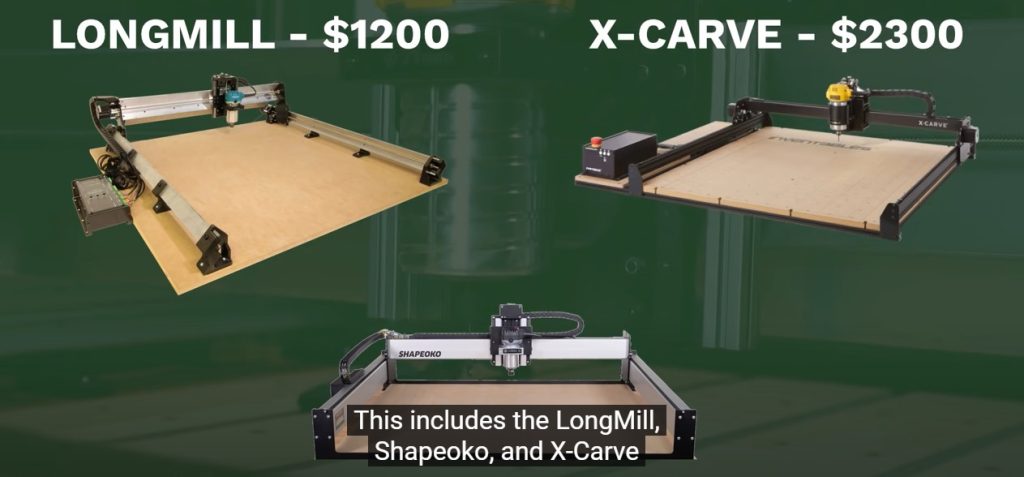
This post will focus on 3-axis CNC routers, which are the most popular among hobbyists. This includes the LongMill, Shapeoko, and X-Carve to name a few.
CNC Bisic Overview
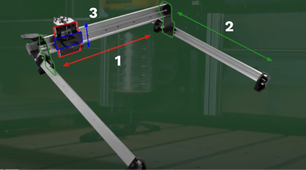
Notice they all have 3 axis,the X, Y, and Z.
The basic workflow required to run these can be broken down into three main sections.
Three Common Step
First, you come up with a really clever design on the computer.
Second, you take the design and create instructions that describe how to carve it.This process is called CAM, more on that later.
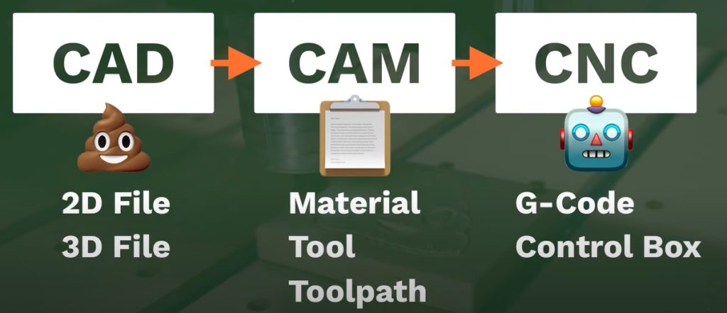
Third, we need to hand these instructions over to the machine. This is usually done with a digital interface. We can then hit the start button and the machine will cut out the design. Of course, each of the three sections has many different subsets.
What is CAD?
Let’s take a deeper dive into each section. The first step of the process is often referred to as CAD, that stands for Computer-Aided Design. It simply means we’re using computer software to create the design. This is where most beginners start to sweat. But I promise you, it’s not as hard as it seems.
For starter projects, you can use simple 2D graphic programs like Inkscape or Illustrator. The other end of the spectrum is professional-level CAD programs like SolidWorks or Fusion 360. In between, are programs created specifically for hobbyists CNC machines like CAMLab, Carbide Create, and Easel. Which software you choose will also depend on the type of cut you’re trying to create.
3 Different Cutting Strategies
Most CNC projects use one of three different cutting strategies.
First, we have 2D cuts. These are when we simply have the machine trace an object and cut it out. Things like letters and basic shapes. Second, we have the three dimensional cuts, where the machine is using all three axes at the same time. This method is used for more complex projects.
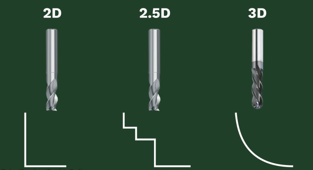
In between these two, we have 2.5D. This is when we’re just following simple shapes like regular 2D cuts, but we tell the machine to cut deeper in a certain area. It’s not a true 3D cut because the Z-axis never moves at the same time as the Y or X-axis. I went ahead and sketched out the ice cream emoji in Fusion 360.
I could technically leave this as a 2D sketch, but I’ll turn it into a 3D body so it’s easier to see what we’re cutting. Comment below which of the three cutting strategies you think this design requires. Once we’ve created the design, we need to create the instructions for the machine.
What is CAM?
This second step uses CAM, or Computer-Aided Manufacturing. That means we’re using a computer to control a machine that can manufacture things.
Remember, CAD is design and CAM is manufacturing. Fusion 360 is my personal software choice because it does CAD and CAM in the same piece of software.It’s also free for hobbyists to use. You can also learn Fusion 360 right here on my YouTube channel. The first step when creating our CAM instructions is to define our material.
I’m going to cut the ice cream emoji out of some scrap wood, so I’ll enter the dimensions in Fusion 360. Second, we need to choose our cutting tool. Cutting tools will have to be a separate video, but the number one takeaway is that our cutting tool must be smaller than the objects we want to cut. A 1/4 inch end mill physically can’t drill an 1/8 inch hole. So we need to tell the software which tool we’re using to make sure it will work with our shape.
Speed and Feed explained
We can also define the speeds and feeds. This concept is one that often intimidates newbies, but it’s much simpler than most think. The cutting speed is defined as how fast the cutting tool moves in relation to the material.
You can think of this as the speed limit. The feed rate is defined as the distance the tool travels during one revolution of the tool.
Most hobbyist projects are for common materials like MDF, plywood, or hardwoods. Thus, we can simply copy and paste the ideal numbers from online cheat sheets. You don’t need a Math or Engineering Degree. These cheat sheets are a great starting point when you’re just getting started, and you’ll eventually learn which speeds and feeds work best for you. Once our material and bit info is defined, we need to write the body of the instructions.This is where we tell the software what shapes to cut out.

What is a toolpath?
We refer to these as the toolpaths, or the path through space that our cutting tool follows. How you achieve this will differ from software to software. But as you can see, this is pretty easy in Fusion 360. I’ve set up one toolpath for the inner design and a 2D contour toolpath for the outer shape.The biggest advantage of CAM software is that we can simulate our cut before sending it to the machine. This helps us catch any potential problems before we plow through our material or, even worse, break the machine. Beginners often get frustrated when the machine doesn’t follow the instructions. But the problem lies in the fact that the machine follows all the instructions. When something goes wrong, it’s because we told it an instruction that we didn’t mean to.
We’re done creating our instructions once our setup and toolpaths are complete. At this point, we need to hand them over to the machine. Right now the instructions are on our computer and the machine doesn’t know about them. To get the instructions to the machine, we’ll need to export them in a language that the machine can understand.
What is G-code?
Most machines read something called G-code.
The “G” stands for Geometric. The great thing about G-code is that you don’t ever have to learn how to write it as the software does it all for us. However, as you get more into the world of CNC machines, you’ll find having a basic understanding of G-code will help you avoid unwanted problems. Put simply, G-code is written out to tell the machine where to travel to. Remember our machine has three axes.
For now, let’s forget about the up and down Z-axis.
Our machine now only moves in the X and Y direction. This is similar to a graph where points are plotted on a Cartesian plane. The G-code includes lines of code that plot each shape of the design. Remember our toolpaths?
They dictate what the software includes in the G-code. Now, there’s a little bit more to it than that, but hopefully that gives you a basic idea of what’s going on. Once we have our G-code, we have to find a way to get it to the machine. Hobbyists machines often have a control box that includes a microcontroller, such as an Arduino.
Getting the G-code to the Machine
That means we’ll need to use our computer to communicate with it.
Depending on the machine, this can be done straight from Fusion 360 using a plugin, or we can use GRBL, which is an open-source CNC controller. This lets us open the G-code that was generated by our CAM software. First, we need to strap in our material.
Setting up the Machine
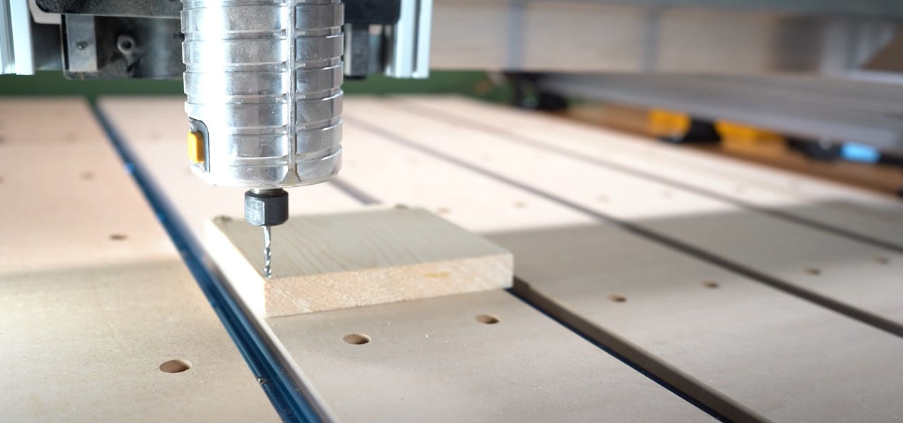
We can simply screw in the material, strap it in place with clamps, use double-sided tape or a vacuum table that sucks the material down. We also need to place the appropriate bit in the collet.
Remember this has to be the same as what we defined in the CAM software.
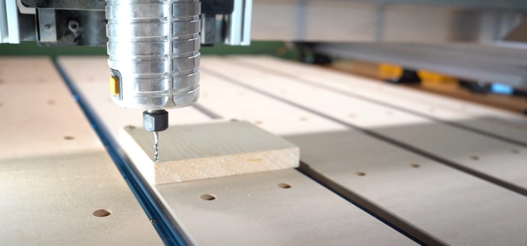
Next, we need to place the machine in its starting position. With most hobbyist machines, we’ll have to do this manually. Most hobbyist machines also require us to manually adjust the speed of the router and turn it on. We can then simply hit the run or play button, and the machine starts to cut.
Cross our fingers that our instructions only include what we want. Remember, if the machine travels where we don’t want it to, then it’s because we told it to do something that we shouldn’t have.
Most errors are caused by including features or settings without knowing it. Thanks for sticking around to the end of this video. You can help me out by hitting that like button for me.